
|
back to www.audiodesignguide.com |
To get more information contact me at: webmaster@audiodesignguide.com |
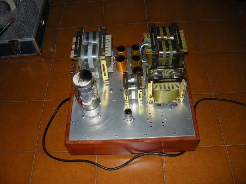
GM70 amplifier
with Fiat transformers
started on September 15 st , 2009
BEWARE! This is
an expert-only project because the high power supply voltage, about 1KV. Be
careful, it can kill you!
Keep always one hand (better if it is the left hand) behind your back.
INTRODUCTION
After 2 years of tests I have develop with Fiat srl and Walter Gentilucci an output transformer with the following specifications:
In this amplifier I
will try to use the stacked power supply configuration to skip the inter stage
capacitor so a dc coupled.
In any case the inter stage capacitor change the sound of the amplifier so to
get a good result it is necessary use hi-end capacitors like the
Jensen Copper film paper in oil
but these are expensive like an inter stage transformer.
The stacked power supply configuration in a two stage only amplifier is a good
and simple solution.
Normal DC coupled amplifier, like the Loftin White, give always problems because
the bias points change in the time but in the stacked configuration there are no
problems because the output tube have a fixed bias like in the normal amplifier.

The my choice for this
project is the GM70 because in a direct comparison with the 845, the
GM70 have the same
sound quality.
The main advantage of the GM70 is the high voltage gain so it is possible to use
a simple one stage driver stage.
I have used a load of about 10Kohm to get a good damping factor (less than
2ohm) and an anode voltage of 900V to get a power about 16-17w.

Also the 70H choke for the driver has
been develop by Fiat on my specifications: 70H 680ohm and an air gap able to
support 20mA DC current.
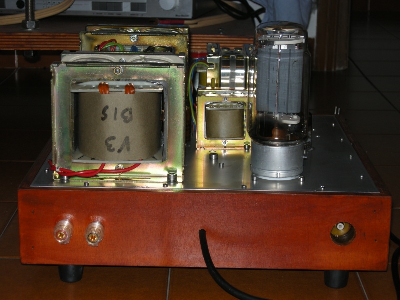
Two mono-block will have an external size
of only 40 x 40 cm.
TUBES
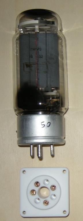 |
GM70 copper plate
specifications:
The sockets show has been created by Jakeband, he produce a very good teflon socket with copper terminal at a right price. For the GM70 if you don't like teflon sockets it is possible convert a 813 ceramic socket increasing the size of only one pin.
|
D3A specifications in triode
connection:
|
6C45 specifications:
|
To create a GM70
single ended amplifier with enough sensibility to be driver directly by a CD
player or a phono preamplifier it is necessary have a driver stage with a
voltage gain about 50x or 70x.
Using the pentode
D3a
in triode connection it is possible
build a pure single ended two stages amplifier because it have high gain and low
internal resistance.
In this amplifier it is possible to use the Russian 6C45
(instead of D3a) without many changes (disconnect only 2 pin on the socket) but
in this case will be necessary 1.5Vrms in input (instead of 1Vrms) to drive this
amplifier.
This amplifier have enough power (about
16w) and low output impedance (less than 2ohm) to drive any kind of loudspeakers like full range, low efficiency
with 2 or 3 ways and also any electrostatic.
The max power is the measurement result increasing the output level until
the distortion spectrum decay is perfect but this amplifier will support larger
peaks in less linear area.
I suggest this project only to person with some experience with vacuum tubes
amplifier because it use very high voltage so it is necessary be care and use
only good wire for the internal cabling.
A very good quality stranded tinned copper
wire could be buy directly from
E-Z-HOOK
that carries an extensive line of fine stranded and extra flexible wire.
I have used the model 9506 with WVDC (Working Voltage Direct Current ) of 5000V
for all the main power supply connections, the model 9501 for the input signal
and the model 9505 for the medium voltage.
All the wires near the tube socket have been cover by Sterling tubes in order to
avoid that the high temperature will destroy them.
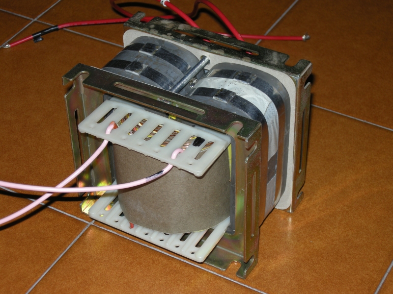
The two power supply transformers should be custom made and these could be
toroidal, double c-core or r-core type but in any case it is very important to
keep the flux low, 20% less than normal (14000 instead of 17000) and 2
mm²
per ampere.
In the 845 amplifiers it is possible use ac filaments reducing the noise with
simple 100ohm 3w trimmer and dc filaments are necessary only with if you have very
high efficiency loudspeakers (about 100db).
The GM70 require dc filaments with any kind of loudspeakers due to the higher
amplification factor and the trimmer are useless.
Any amplifiers with dc filaments should use a separated transformer for the
filaments because using a single transformer the noise generated by the
rectification process in input capacitor power supply is amplified to the anodic
secondaries .
Follows the operating point choice for the GM70.

TRANSFORMES
see Introduction.
MEASUREMENTS DRIVER STAGE
The environment is:

The value will be optimized on final amplifier with both stages.
FINAL MEASUREMENTS
The environment is:
1.7% at 10.2Vrms => 13W on 8ohm
2.0% at 11.5Vrms => 16W on 8ohm
Follows the frequency response using 100ohm and 440uF on catode (15Hz - 20KHz at -1dB).

Follows the frequency response using the led on cathode (20Hz - 20KHz at -1dB).
In this case there is no resonance on low frequency because no cathode cap.
SCHEMATIC
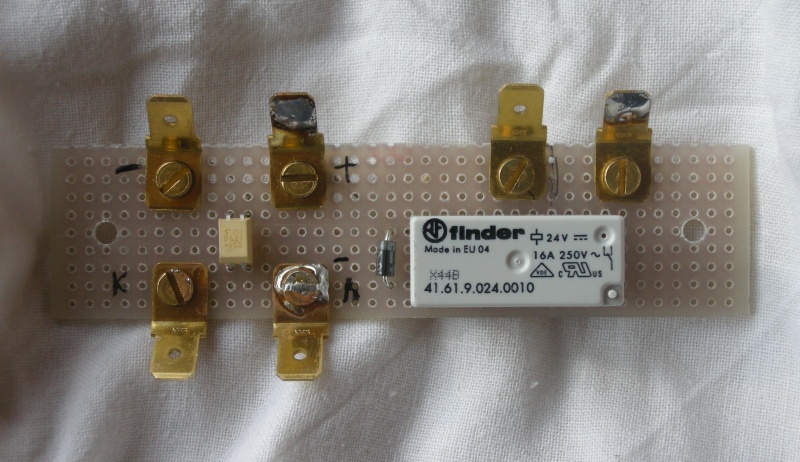
In the dc coupled amplifiers the start-up phase is critical because the input stage can give alteration on GM70 grid changing the bias point.
To skip the startup-up problem the GM70
anode power supply is applied with a delay.
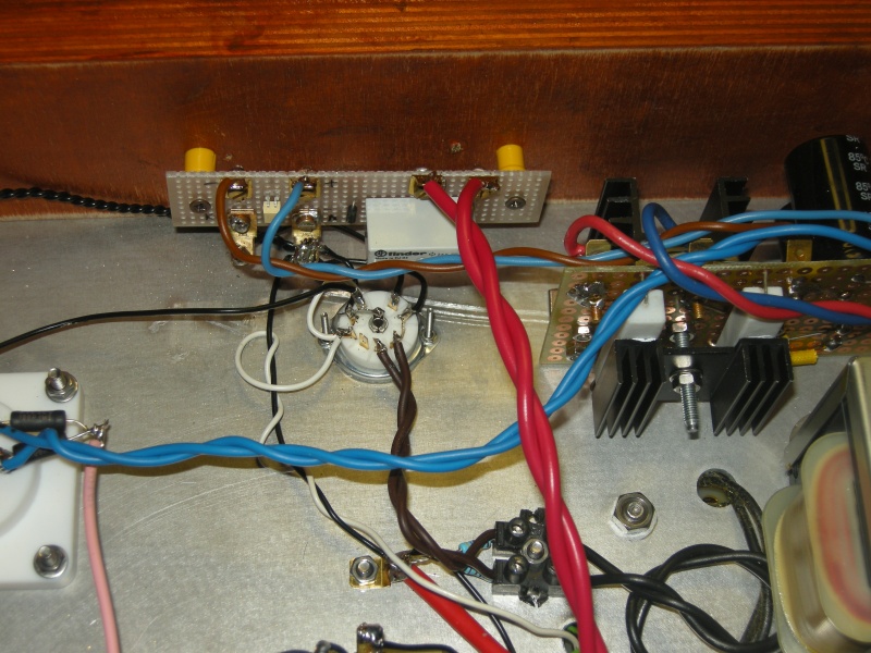
I have used an
photo coupler instead of a fix
delay circuit because this can work better and faster.
The time for this delay will be exactly what is necessary
because the relay switch when the driver stage is active.
Inside the TLP621 photo coupler there is a led and a
photo transistor and in this schematic the led is on cathode of driver vacuum
tube.
On many forum there are
good opinions about the sound of led used like cathode bias and these confirm my
listen tests.
The sound using the
photo coupler is more neutral of
the normal capacitor-resistor version.
If you don't trust the led sound you can add a capacitor in parallel to the
TLP621
input pins.
In the following plots are clear the differences of the two versions in a WinSpice simulation, with the bias led and with normal resistance/capacitor on cathode.
The frequency response is different only on low frequency band because with the led there is no resonance and the distortion as decay and as level are very similar.
 |
 |

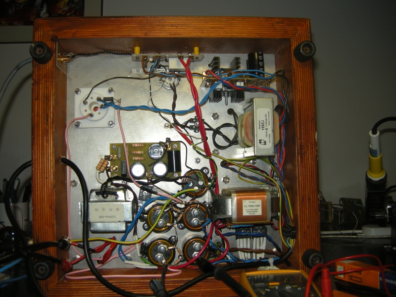
POWER SUPPLY
The two power supply are custom made on my specifications with the 80% of normal flux.
Some secondaries could be merged to reduce the final cost (10v+10v 4A => 20v and 340v+340v 0.4A => 680v).
If you use a single 680v secondary a custom made diode bridge with 2 x 1N5406 or 2 x UF5408 in series should be used.
Many power supply choke could be used but different value of static resistor (Rdc) will change the output voltages so you need to recalculate the transformer secondary voltages.
You can use the freeware PSU designer II by Duncan Amplification to design your power supply, follows some file to start. .
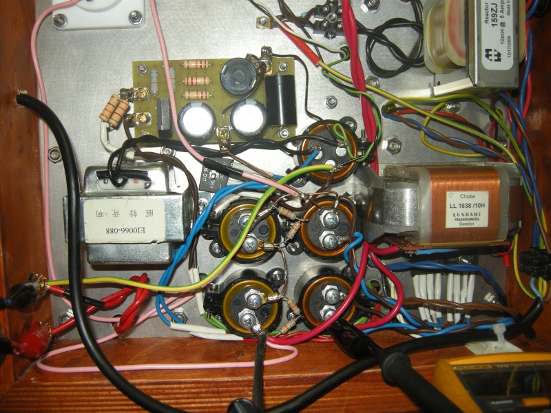
The little 10H 100mA DCR=470ohm on D3a power supply is a EI66-88 now available on Diy Club webshop with a different case at only 12$.
The big 10H 150mA DCR=36ohm used on
GM70 anode power supply is a
LL1638/10H by
Lundahl at 100$.
For the GM70 filament has been used a cheap
Hammond 159ZJ with a gap to
support until 5A available at 30$.


MATERIAL SOURCES
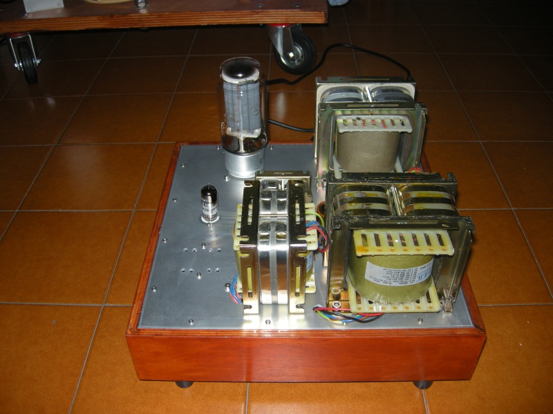
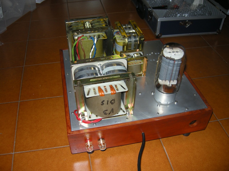
PHOTOS

