
|
back to www.audiodesignguide.com |
To get more information contact me at: webmaster@audiodesignguide.com |
USB DAC 2a - Hi-Resolution System
April
1 st , 2012 -
working in progress ......


INTRODUCTION
Main specifications:
- XMOS USB Audio 2.0
- Asynchronous USB to I2S
- Supports standard sample rates - 44.1kHz, 48kHz, 88.2kHz, 96kHz, 176.4kHz, 192kHz
- AD1955 Hi-end 24 bit 192KHz DAC
- Passive I/V with Caddock MK132 resistor
- Tent Labs shunt regulator
- Hybrid vacuum tube output stage
- Low output impedance
- No feedback
- Volume control with remote control
- Mute hardware control with remote control
- Soft-start for filaments
- Dual mono Virtual Battery operation
- MKP power supply
- Balanced and un-balanced output

modular design


XMOS MODULE
I have tested these USB-I2S interfaces and I have found very big differences in the sound:
After 3 tests in 2 different rooms, 3 different systems, with 3 my friends I can affirm that XMOS module by Lorien is the best. There are many differences in the listening and only the XMOS has an open sound, full of details and never tiring. With the XMOS all musical instruments are easily recognizable in the sound stage.

AD1955 DAC MODULE SCHEMATIC
The DAC module use a dedicated power supply with a separated
section for the analog stage.
A passive I/V has been created using Hi-end MK132 Caddock
resisors.
The pcb use AD1955 mounted on DIP adapter to be simple for DIY.

 |
I have tested 3
different regulators on AD1955 DAC analog power supply. 1) LT1086-5 considered a very good series regulator for audio 2) A very low noise shunt with no op-amp similar to Salas design 3) Tent Labs shunt The low noise shunt sound a little better than LT1086-5 but the Tent Labs shunt sound much more better. The sound with Tent Labs shunt is another world, all instruments and voices are distinguishable and separate. This shunt allows a great increase in the quality of the reproduced sound. |
AD1955 DAC MODULE PCB


CONTROLLER MODULE SCHEMATIC
To use the AD1955 DAC chip with many sampling
frequencies is necessary to set the internal register of this chip following
this table.

Others DAC chips
like the TI PCM1794 and Wolfson
WM8740 has a master clock detection circuit that
automatically determines the relationship between the master clock frequency
and the sampling rate.
In a
direct comparison the AD1955 sound much better than PM1794 and WM8740
but you can use the same output module with these DAC chips and in these
case you don't need the controller module.
The AD1955 have an on-chip click less analog volume control without lost in resolution and I have implemented this in the PIC firmware so we can save the money necessary to buy a DACT stepper attenuator.
In my first test I have used a little PIC to have only basic functions but in order to display volume level, input sampling frequency, USB link status and to have a remote command as been used a large PIC Microcontroller.
The controller module can be configurated for other functions like a stand-by to power-on manager with a separated transformer.

CONTROLLER MODULE PCB

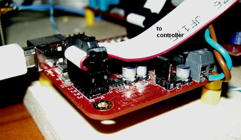
CONTROLLER MODULE PHOTOS
 |
|


CONTROLLER MODULE FIRWARE
 |
To program the 16F877A Microchip microcontroller I have used the PICKIT 2 USB Development Programmer/Debugger (cod. PG164120 or DV164121) with a cost about 40-50$. |
I love the C language because it is very simple if compared to assembler.
 |
The my C source has been
compiled with HI-TECH
PICC-Lite™ Compiler
V9.82 for PIC10/12/16 MCUs. HI-TECH Software has provided a freeware HI-TECH PICC-Lite compiler as a tool for hobbyists and students, but the licence allows its use for commercial purposes as well. It is ideal as a teaching tool for an introduction into the 'C' language and embedded programing on a Microchip device. |
Here you can download the last version of source and hex files.
The hex file is ready to program the chip with PICKIT 2 but if you want to compile this source code use the following line command:
"C:\Programmi\HI-TECH Software\PICC\9.82\bin\picc.exe" -16F877 Control22a.c
OUTPUT STAGE SCHEMATIC
My Hybrid output stage has been designed many years ago for an Italian company
and it is used in a top level CD Player (value about 7000 euro).
The power supply use a 3A adjustable regulator LM350 with a soft start for the filaments
at 12.6V DC and a dual mono Virtual Battery for the high voltage about 270V DC.
There are only 2 big 39uF 400V Solen MKP on the output of each power supply to
get the best sonic performances.
As output capacitors I suggest to use only 2.2uF Jantzen Superior Z-Cap to
extract all the details.
It is necessary an output relay to prevent the output of the voltage peaks
during the switching on and off so this is integrated in the pcb.
Only two AC voltage are necessary, 220Vrms AC for the anodic and 15Vrms AC for
the filaments, for the delay circuit with relays and also for the negative
current generator of the differential amplifier.
In the PCB are present the components to create a version with balanced and
unbalanced outputs but if you don't need balanced output simply do not fit some
components (Q4-5, R66-67, R72-73, R35-38, R39-42, R43-44. R45-46, 2 x 2.2uF).
In the power supply has been used 2 x
IRF740 and in the output stage
4 x IRF720.

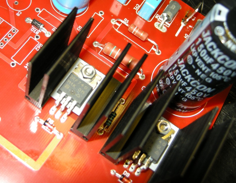
PCB OUTPUT STAGE

TRANSFORMER
The power supply transformer has been
created on my specification with an extreme low flux by
Italtras.
The primary has been calculated for 260V instead of 220V to keep the flux at
14000 gauss instead of normal 17000 gauss.
| primary | primary | |||||
| 220 | 260 | |||||
| secondaries | current | VA | secondaries | current | VA | |
| 220 | 0.3 | 66 | 260 | 0.3 | 78 | |
| 15 | 2 | 30 | 17 | 2 | 34 | |
| 9 | 3 | 27 | 10 | 3 | 30 | |
| total | 123 | total | 142 |

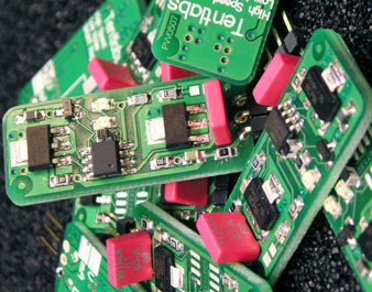
PHOTO


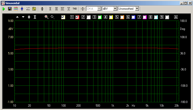
MEASUREMENTS

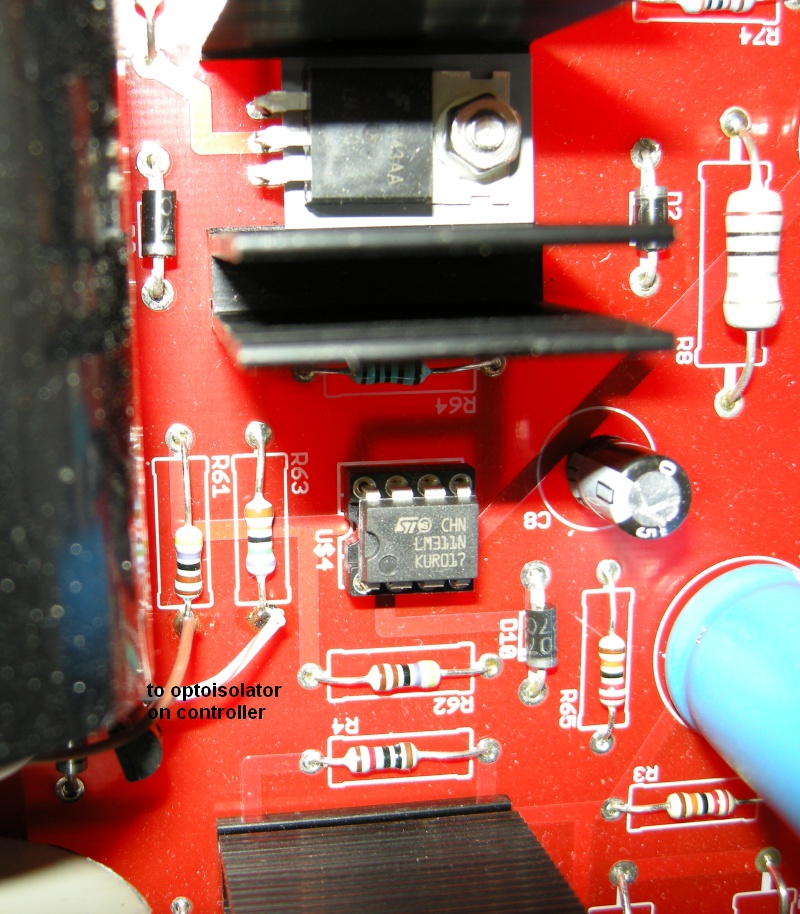
DETAILS
I have used this type of heat sink for all the mosfets and for the linear regulator:


 |
|
PCB FILES