Here there is an article of Martin J. King about a comparison of the Bass Performance of Open Baffle, U Frame, and H Frame Speakers.
To compensate the normal loss of efficiency of the dipole it is necessary to use a filter, in this case an active filter is placed before a dedicated amplifier.
This active filter increases about 12-15dB at 30Hz therefore it is necessary to use a high power amplifiers and only woofers with large excursions and high power are able to support this conditions.
This project born to be combined with the my new loudspeaker system which use the Purifi mid-woofer and the Mundorf AMT but it can be used in any system with mid-woofer able to produce 80-100Hz.
The first my test of this H-frame subwoofer was on a little 10" Wavecor woofer but this new version with a 18" give a more defined and drier sound, even the mid-frequency range seems cleaner.
BOX DESIGN
The box was built using 25mm MDF.

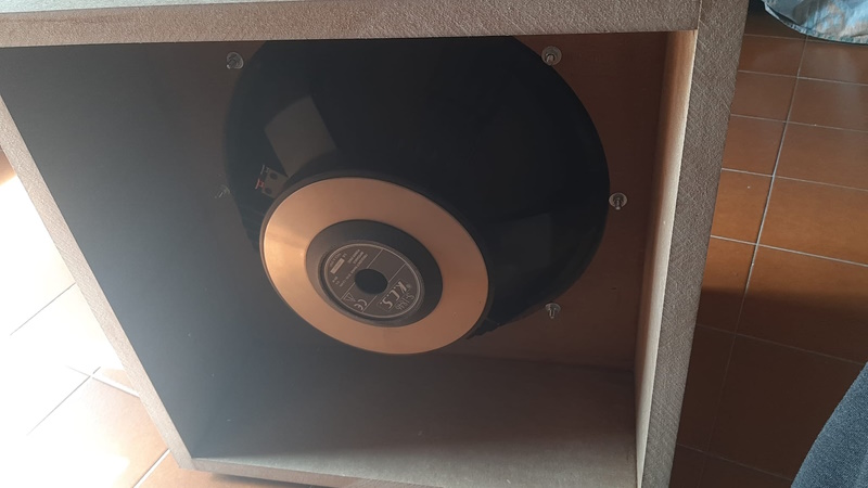
WOOFER
I have used an old K.C.S. 18" S-1846 woofer.
SIMULATION
This H-frame has been simulated using the
Matcad
worksheet
by
Martin King
on a Windows XP virtual machine.
Here has been used the data of the
Faital 18FH510 woofer.


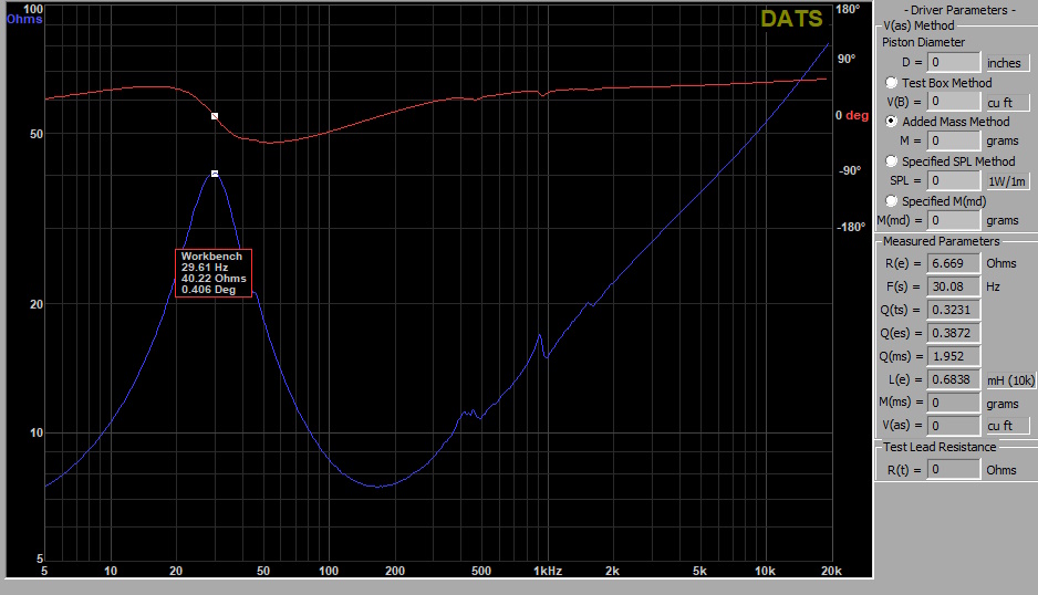
MEASUREMENTS
Follows the frequency response of the loudspeaker with and without the active filter (this is like the simulation model).

OLD ACTIVE FILTER
I have got on Ebay an active crossover module to start like base (NE5532 Subwoofer processing circuit).

The original schematic have a big problem, the output voltage change with the frequency setting.


so I have changed some components and the schematic to obtain a good low-pass and to add a dipole compensation.


The main problem of this previous circuit is the 50Kohm potentiometer for frequency change which is not linear but logarithmic so it is not easy find the right position and the fixed frequency of the second filter.
NEW ACTIVE FILTER
Follows the new filter with a true variable 24dB/oct + dipole compensation


| n. | C1 (nF) | C2 = 2xC1 | R1 and R2 | C1 (F) | C2 (F) | F (Hz) |
| 1 | 150 | 300 | 3570 | 0,000000150 | 0,0000003 | 210,0 |
| 2 | 150 | 300 | 4120 | 0,000000150 | 0,0000003 | 182,0 |
| 3 | 150 | 300 | 4700 | 0,000000150 | 0,0000003 | 159,5 |
| 4 | 150 | 300 | 5490 | 0,000000150 | 0,0000003 | 136,6 |
| 5 | 150 | 300 | 6200 | 0,000000150 | 0,0000003 | 120,9 |
| 6 | 150 | 300 | 7150 | 0,000000150 | 0,0000003 | 104,9 |
| 7 | 150 | 300 | 8250 | 0,000000150 | 0,0000003 | 90,9 |
| 8 | 150 | 300 | 9530 | 0,000000150 | 0,0000003 | 78,7 |
R1
1Kohm 1/4W 1%
R2
100Kohm 1/4W 1%
R3,R11,R19,R27 3570ohm
1/4W 1%
R4,R12,R20,R28 4120ohm 1/4W 1%
R5,R13,R21,R29 4700ohm 1/4W 1%
R6,R14,R22,R30
5490ohm 1/4W 1%
R7,R15,R23,R31 6200ohm 1/4W
1%
R8,R16,R24,R32 7150ohm 1/4W 1%
R9,R17,R25,R33 8250ohm 1/4W 1%
R10,R18,R26,R34
9530ohm 1/4W 1%
R40,R41
270ohm 1/4W 1%
R38,R39
3000ohm 1/4W 1%
R36
56Kohm 1/4W 1%
R35
3Kohm 1/4W 1%
R37
0ohm
C1,C2,C3.C4,C11,C12 0.15uF WIMA MKP
C5,C8
0.22uF WIMA MKP
C6,C7
470uF 35V
C9,C10
100uF 25V
IC1,IC2
NE5532
U$1
LM317
U$2
LM337
B1
diode bridge 1A
SW1,SW2,SW3,SW4 dip switch 8
way
It is necessary a 1uF on output signal to this filter to eliminate very low frequency.
Follows the measurement of this new filter on amplier output in all the dip switch positions..

Follows the measurement of this H-frame subwoofer with this filter in all the dip switch positions.

AMPLIFIER MODULE
These modules are availbale at low cost on Alixpress shop.
L-25D IRAUDAMP9 IRS2092 IRFB4020 Top Class D Audio Amplifier Board 250W*2 8ohm Finished Board.

The L-25D digital
series power amplifier board uses the best performance International
Rectification Company’s Class D power amplifier dedicated driver IC
IRS2092,
and the International Rectification Company’s dedicated digital power
amplifier field effect tube IRFB4020.
Imported original
ultra-low impedance polymer semiconductor solid capacitors are used.
The polymer semiconductor capacitors have ultra-low internal resistance and
ultra-low distortion.
The parameters are as
follows:
- Power supply voltage: DC ±60V to ±80V, recommended voltage ±70V
- Output power: 250W *2 8 ohms (±70V)
- Voltage gain: 40 Size: 130MM*60MM
- Weight: 280g (2 PCS)
- Input sensitivity: 1.6V
- Residual Noise: 200 μV (22 Hz – 20kHz, AES17 filter Self-oscillating frequency)
- THD+N, 100W :0.008% 1kHz, Single-channel driven
- Total Idle Power Consumption 7W No input signal
- Channel Efficiency 90% Single-channel driven, 250W
- Original brand new IC IRS2092SPBF + IRFB4020
700W High Efficiency LLC Switch Amplifier Audio Power Supply Board AC220V Input Output Voltage Dual 60V

The parameters are as follows:
- Input voltage: AC200-240V
- Output main voltage +-60V/6.0A;
- Independent 12V/0.5A;
- Auxiliary +-12V/0.5A (auxiliary and independent are not regulated)
- Voltage regulation accuracy: main no-load ±3%, with load ±3%; (when AC220V input)
- Continuous power: 350W (can work continuously for long-term 350W work at 25°C ambient temperature, fan cooling is required)
- Rated power: 700W (can work continuously for about 5 minutes at 25°C ambient temperature)
- Instantaneous power: 900W (power generated during dynamic signal impact, less than 100 milliseconds)
- Conversion efficiency: Max 98%
- Dimensions: length, width and height = 96*96*38mm
- Weight: 310g
Here is possible to see the signal from the input rca to filter module, to interstage cap 10uF (now 1uF), to the potentiometer for the level control and to output module.

 |
I
have used a DC protection module to save my woofer in case of fault on
switching amplifier. The AIYIMA 2.0 DC protection module on Alixpress with optoisolators is perfect. |

PHOTOS